CAN
Controller Area Network (CAN) is a very common interface in industrial and automotive control. CAN is very robust and works very well in noisy environments at high speeds. All error checking and recovery methods are done automatically on the hardware. TD (Transmit Data) and RD (Receive Date) are the only two pins needed.
There is no master/slave relationship in CAN. All nodes are equal and can both transmit and receive. CAN includes a protocal which easily allows for a node to claim a slice of time for its use so that collisions do not occur. You must have at least two nodes on the bus, however, or CAN will not work.
There are many kinds of physical layers, but the most commonly used is a high-speed-dual wire that uses a twisted pair for noise immunity. This transceiver can run at up to 1 Mbit/s and can transfer data on very long wires if a low bit rate is used. Data can be transferred between nodes on the bus where any node can transfer at any time and all other nodes are required to successfully receive the data. All nodes must have a predefined bit timing criteria. This is much more complicated than calculating a simple baud rate for UART. For this reason, many CAN bit rate calculators are available which you can find using a simple internet search.
We provide a few precalculated speeds that you can use but you can create more precise custom timings if you wish. There is an informative CAN guide in our downloads.

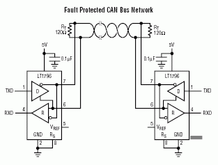
The above image shows two CAN nodes connected over a bus with the 120 ohm resistors required on these transceivers.
Tip
Make sure to check the datasheet from the tranceiver. Most CAN controllers will divide the frequency by 2 before actually using it.
Getting Started
The code below sends a message over the CAN bus and prints out every message it receives to the debug window. It requires the GHI.Hardware assembly be added to the resources in your Visual Studio project.
using GHI.IO;
using Microsoft.SPOT;
using System.Threading;

public class Program
{
    public static void Main()
    {
        var can = new ControllerAreaNetwork(ControllerAreaNetwork.Channel.One, ControllerAreaNetwork.Speed.Kbps1000);

        can.ErrorReceived += can_ErrorReceived;
        can.MessageAvailable += can_MessageAvailable;

        can.Enabled = true;

        can.SendMessage(new ControllerAreaNetwork.Message() { Data = new byte[] { 0x01, 0x02, 0x03, 0x04, 0x05, 0x06, 0x07, 0x08 }, ArbitrationId = 0x12345678, Length = 8, IsRemoteTransmissionRequest = false, IsExtendedId = true });

        Thread.Sleep(Timeout.Infinite);
    }

    private static void can_MessageAvailable(ControllerAreaNetwork sender, ControllerAreaNetwork.MessageAvailableEventArgs e)
    {
        var received = sender.ReadMessage();

        var data = string.Empty;
        for (int i = 0; i < received.Length; i++)
            data += "0x" + received.Data[i].ToString("x2") + " ";

        Debug.Print("   CAN Message   ");
        Debug.Print("-----------------");
        Debug.Print("    ID: " + received.ArbitrationId.ToString());
        Debug.Print("  Time: " + received.TimeStamp.ToString());
        Debug.Print("   RTR: " + received.IsRemoteTransmissionRequest.ToString());
        Debug.Print("   EID: " + received.IsExtendedId.ToString());
        Debug.Print("Length: " + received.Length.ToString());
        Debug.Print("  Data: " + data);
        Debug.Print("");
    }

    private static void can_ErrorReceived(ControllerAreaNetwork sender, ControllerAreaNetwork.ErrorReceivedEventArgs e)
    {
        Debug.Print("Error on CAN: " + e.Error.ToString());
    }
}
CAN Bit Timing Settings
The following CAN bit timing parameters were calculated for a SITCore driving the SN65HVD230 CAN transceiver chip. See the CAN Tutorial for more information.
| Baud | Propagation | Phase1 | Phase2 | Baudrate Prescaler | Synchronization Jump Width | Use Multi Bit Sampling | Sample Point | Max Osc. Tolerance | Max Cable Length |
|---|---|---|---|---|---|---|---|---|---|
| 33.333K | ? | ? | ? | ? | ? | False | 86.7% | 0.33% | 2145M |
| 83.333K | ? | ? | ? | ? | 1 | False | 88.9% | 0.28% | 879M |
| 125K | ? | ? | ? | ? | 1 | False | 87.5% | 0.31% | 545M |
| 250K | ? | ? | ? | ? | 1 | False | 88.9% | 0.28% | 257M |
| 500K | ? | ? | ? | ? | 1 | False | 88.9% | 0.28% | 101M |
| 1M | ? | ? | ? | ? | 1 | False | 88.9% | 0.28% | 23M |
Note: Maximum Oscillator Tolerance and Maximum Cable Length are theoretical maximums and must be tested to ensure reliability.