.NET Gadgeteer Intro
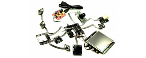
.NET Gadgeteer is a discontinued technology that was initiated by Microsoft Research and taken to production by GHI Electronics in the year 2011. .NET Gadgeteer had a great few year run, where it was loved for its plug-and-play mainboard and modules.
Tip
We will refer to .NET Gadgeteer as Gadgeteer throughout the rest of the documentation.
The core of .NET Gadgeteer is .NET Micro Framework (NETMF). Like Gadgeteer, NETMF is no longer evolved by Microsoft and left for the community. Learn more about NETMF
Sadly, and after 5 years of building modules and mainboards, GHI Electronics had to announce the EOL for Gadgeteer; however, most of the Gadgeteer hardware can still be used with TinyCLR OS.
External resources:
- Microsoft's .NET Gadgeteer website (down) http://www.gadgeteer.com/
- Microsoft's NETMF website (outdated) http://www.netmf.com/
Most of the Gadgeteer ecosystem is open-source:
- Microsoft's .NET Gadgeteer Core
- GHI Electronics' Software sources and Hardware design files
Socket Map
The magic of Gadgeteer is in its socket map
| Socket | Pin1 | Pin2 | Pin3 | Pin4 | Pin5 | Pin6 | Pin7 | Pin8 | Pin9 | Pin10 |
|---|---|---|---|---|---|---|---|---|---|---|
| A | +3.3V | +5V | AIN (G!) | AIN (G) | AIN | GPIO | [UN] | [UN] | [UN] | GND |
| B | +3.3V | +5V | LCD B0 | LCD B1 | LCD B2 | LCD B3 | LCD B4 | LCD ENABLE | LCD CLK | GND |
| C | +3.3V | +5V | GPIO! | CAN TD (G) | CAN RD (G) | GPIO | [UN] | [UN] | [UN] | GND |
| D | +3.3V | +5V | GPIO! | D- | D+ | GPIO | GPIO | [UN] | [UN] | GND |
| E | +3.3V | +5V | [UN] | LED1 (OPT) | LED2 (OPT) | TX D- | TX D+ | RX D- | RX D+ | GND |
| F | +3.3V | +5V | GPIO! | DAT0 | DAT1 | CMD | DAT2 | DAT3 | CLK | GND |
| G | +3.3V | +5V | LCD G0 | LCD G1 | LCD G2 | LCD G3 | LCD G4 | LCD G5 | LCD BACKLIGHT | GND |
| H | +3.3V | +5V | GPIO! | D- | D+ | [UN] | [UN] | [UN] | [UN] | GND |
| I | +3.3V | +5V | GPIO! | [UN] | [UN] | GPIO | [UN] | SDA | SCL | GND |
| K | +3.3V | +5V | GPIO! | TX (G) | RX (G) | RTS | CTS | [UN] | [UN] | GND |
| O | +3.3V | +5V | GPIO! | GPIO | AOUT | [UN] | [UN] | [UN] | [UN] | GND |
| P | +3.3V | +5V | GPIO! | [UN] | [UN] | GPIO | PWM (G) | PWM (G) | PWM | GND |
| R | +3.3V | +5V | LCD R0 | LCD R1 | LCD R2 | LCD R3 | LCD R4 | LCD VSYNC | LCD HSYNC | GND |
| S | +3.3V | +5V | GPIO! | GPIO | GPIO | CS | MOSI | MISO | SCK | GND |
| T | +3.3V | +5V | [UN] | YU | XL | YD | XR | [UN] | [UN] | GND |
| U | +3.3V | +5V | GPIO! | TX (G) | RX (G) | GPIO | [UN] | [UN] | [UN] | GND |
| X | +3.3V | +5V | GPIO! | GPIO | GPIO | [UN] | [UN] | [UN] | [UN] | GND |
| Y | +3.3V | +5V | GPIO! | GPIO | GPIO | GPIO | GPIO | GPIO | GPIO | GND |
| Z | +3.3V | +5V | [MS] | [MS] | [MS] | [MS] | [MS] | [MS] | [MS] | GND |
| * | +3.3V | +5V | GPIO! | GPIO | GPIO | [MS] | [MS] | [MS] | [MS] | GND |
| Symbol | Description |
|---|---|
| AIN | Analog input pin. |
| GPIO | A general-purpose digital input/output pin, operating at 3.3 volts. |
| (G) | In addition to another functionality, a pin that is also usable as a GPIO. |
| [UN] | Modules must not connect to this pin if using this socket type. Mainboards can support multiple socket types on one socket, as long as individual pin functionalities overlap in a compatible manner, so that a pin from one socket type can overlap with a [UN] pin of another. |
| ! | Interrupt-capable and software pull-up capable GPIO (the pull-up is switchable and in the range of 10,000 to 100,000 ohms). |
| +3.3V | Connection to the +3.3 V power net. |
| +5V | Connection to the +5 V power net. |
| GND | Connection the power ground net. |
Using .NET Gadgeteer
To use .NET Gadgeteer's legacy software, install:
- Visual Studio 20013 (community edition is also supported)
- Unzip and install netmfvs2013.vsix and MicroFramewrokSDK.msi from here
- Microsoft's Gadgeteer Core
- GHI Electronics' NETMF SDK. The latest is recommended.
The Gadgeteer for Beginners guide is a good starting point.
Tip
You can only use Visual Studio 2013, not a newer edition, unless you are using your Gadgeteer hardware with TinyCLR OS.
With TinyCLR OS
Most of the .NET Gadgeteer devices are still usable today, and with the latest technologies, thanks to efforts by GHI Electronics and the community.
It all started in this video!
This means you can still use all your beloved .NET Gadgeteer gear with TinyCLR OS.
The first step needed to use TinyCLR OS is to load the GHI Electronics Bootloader v2 onto your mainboard, then use that to load the TinyCLR OS firmware. Each mainboard product page includes the needed instructions. Once those are loaded, you can start blinking the debug LED, detailed in the next section.
Blinking the LED
Tip
If you have never used TinyCLR OS before, start here
This example will blink the debug LED. You only need to add a power module to your mainboard.
using System.Threading;
using GHIElectronics.TinyCLR.Devices.Gpio;
using GHIElectronics.TinyCLR.Pins;

class Program {
    static void Main() {
        var led = GpioController.GetDefault().OpenPin(FEZSpider.GpioPin.DebugLed);
        led.SetDriveMode(GpioPinDriveMode.Output);

        while(true) {
            led.Write(GpioPinValue.High);
            Thread.Sleep(200);
            led.Write(GpioPinValue.Low);
            Thread.Sleep(200);
        }
    }
}
Tip
The complete pin mapping is made available through GHIElectronics.TinyCLR.Pins. You should not need to use any schematics.
Replace FEZSpider with your mainboard's name.
Adding Gadgeteer Modules
You are now ready to start adding modules.