.NET Gadgeteer Modules
This page lists all .NET Gadgeteer modules. All sources are found on the NETMF and Gadgeteer repo
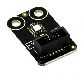
Accel G248
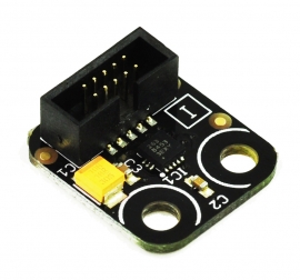
The Accel G248 measures acceleration though I2C bus.
Barometer
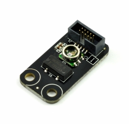
Measures pressure.
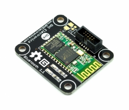
Bluetooth
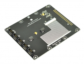
Breadboard X1
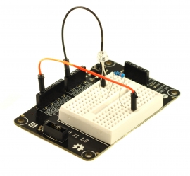
An easy breadboard option. Simply access the socket directly to wire whatever your heart desires!
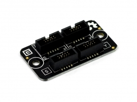
Breakout
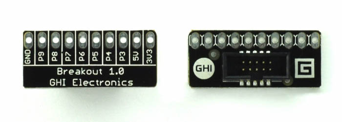
Simply a breakout of all signals.
Breakout TB10
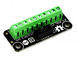
Simply a breakout of all signals, on a terminal block.
Button
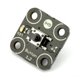
The Button module is very simple, with a button connected to pin 3 and an LED connected to pin4.
Button S7
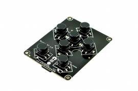
7 buttons on a single module, with LEDs that light up with button presses!
Use the same code example provided for the Button Module.
Buttons map:
Left: Pin
Right: Pin 8
Up: Pin 6
Down: Pin 7
Enter: Pin 3
Back: Pin 4
Forward: Pin 9
CAN DW
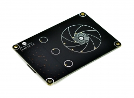
Camera
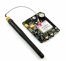
Cellular Radio
Character Display
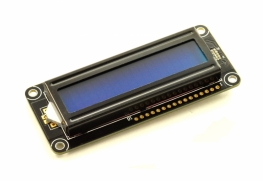
This is a standard and very common HD44780 display.
ColorSense
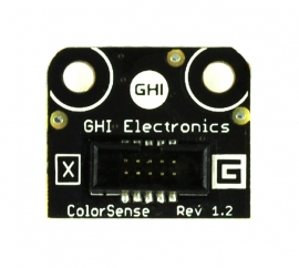
A color sensor that uses software I2C, not yet supported in TinyCLR OS.
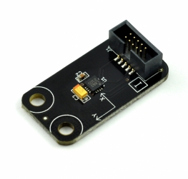
Compass
Current ACS712
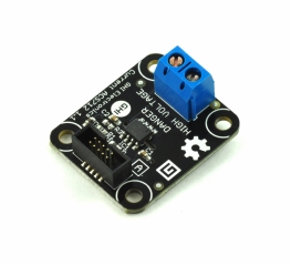
This is a current sensor that uses ACS712, which simply outputs an analog voltage.
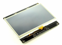
Display CP7
The configurations for the display:
// these are the wrong values!
Width = 800,
Height = 480,
PixelClockRate = 24 * 1000 * 1000,
PixelPolarity = false,
OutputEnablePolarity = true,
OutputEnableIsFixed = true,
HorizontalFrontPorch = 16,
HorizontalBackPorch = 46,
HorizontalSyncPulseWidth = 1,
HorizontalSyncPolarity = true,
VerticalFrontPorch = 7,
VerticalBackPorch = 23,
VerticalSyncPulseWidth = 1,
VerticalSyncPolarity = true,
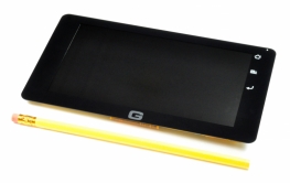
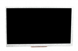
Display N18
This is an SPI display that can work on any system with SPI bus, even small ones without TFT display support.
Display N7
The configurations for the display:
Width = 800,
Height = 480,
PixelClockRate = 24 * 1000 * 1000,
PixelPolarity = false,
OutputEnablePolarity = true,
OutputEnableIsFixed = true,
HorizontalFrontPorch = 16,
HorizontalBackPorch = 46,
HorizontalSyncPulseWidth = 1,
HorizontalSyncPolarity = true,
VerticalFrontPorch = 7,
VerticalBackPorch = 23,
VerticalSyncPulseWidth = 1,
VerticalSyncPolarity = true,
Display NHVN
This allows the use of several displays offered by http://newhavendisplay.com/
Supported displays:
- NHD-4.3-480272EF-ATXL#
- NHD-4.3-480272EF-ATXL#-CTP
- NHD-4.3-480272EF-ATXL#-T
- NHD-7.0-800480EF-ATXL#
- NHD-7.0-800480EF-ATXL#-CTP
- NHD-7.0-800480EF-ATXV#
- NHD-7.0-800480EF-ATXV#-CTP
The configurations for all 4.3" display:
Width = 480,
Height = 272,
PixelClockRate = 20 * 1000 * 1000,
PixelPolarity = false,
OutputEnablePolarity = true,
OutputEnableIsFixed = false,
HorizontalFrontPorch = 2,
HorizontalBackPorch = 2,
HorizontalSyncPulseWidth = 41,
HorizontalSyncPolarity = false,
VerticalFrontPorch = 2,
VerticalBackPorch = 2,
VerticalSyncPulseWidth = 10,
VerticalSyncPolarity = false,
The configurations for all 7" display:
Width = 800,
Height = 480,
PixelClockRate = 20 * 1000 * 1000,
PixelPolarity = false,
OutputEnablePolarity = true,
OutputEnableIsFixed = false,
HorizontalFrontPorch = 88,
HorizontalBackPorch = 40,
HorizontalSyncPulseWidth = 48,
HorizontalSyncPolarity = false,
VerticalFrontPorch = 13,
VerticalBackPorch = 32,
VerticalSyncPulseWidth = 3,
VerticalSyncPolarity = false,
As for the capacitive touch controller, use this old NETMF driver code as a reference:
public class FT5306Controller {
    private InterruptPort touchInterrupt;
    private I2CDevice i2cBus;
    private I2CDevice.I2CTransaction[] transactions;
    private byte[] addressBuffer;
    private byte[] touchDataBuffer;
    private byte[] touchCountBuffer;

    public delegate void TouchEventHandler(FT5306Controller sender, TouchEventArgs e);

    public event TouchEventHandler TouchDown;
    public event TouchEventHandler TouchUp;
    public event TouchEventHandler TouchMove;

    public FT5306Controller(Cpu.Pin interruptPin) {
        this.transactions = new I2CDevice.I2CTransaction[2];
        this.addressBuffer = new byte[1];
        this.touchDataBuffer = new byte[4];
        this.touchCountBuffer = new byte[1];
        this.i2cBus = new I2CDevice(new I2CDevice.Configuration(0x38, 400));
        this.touchInterrupt = new InterruptPort(interruptPin, false, Port.ResistorMode.Disabled, Port.InterruptMode.InterruptEdgeBoth);
        this.touchInterrupt.OnInterrupt += (a, b, c) => this.OnTouchEvent();
    }

    private void OnTouchEvent() {
        var points = this.ReadData(2, this.touchCountBuffer)[0];

        for (var i = 0; i < points; i++) {
            var data = this.ReadData(i * 6 + 3, this.touchDataBuffer);
            var flag = (data[0] & 0xC0) >> 6;
            var x = ((data[0] & 0x0F) << 8) | data[1];
            var y = ((data[2] & 0x0F) << 8) | data[3];

            var handler = flag == 0 ? this.TouchDown : flag == 1 ? this.TouchUp : flag == 2 ? this.TouchMove : null;

            if (handler != null)
                handler(this, new TouchEventArgs { X = x, Y = y });
        }
    }

    private byte[] ReadData(int address, byte[] resultBuffer) {
        this.addressBuffer[0] = (byte)address;

        this.transactions[0] = I2CDevice.CreateWriteTransaction(this.addressBuffer);
        this.transactions[1] = I2CDevice.CreateReadTransaction(resultBuffer);

        this.i2cBus.Execute(this.transactions, 500);

        return resultBuffer;
    }

    public class TouchEventArgs : EventArgs {
        public int X { get; internal set; }
        public int Y { get; internal set; }
    }
}
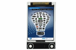
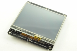
Display T35
The configurations for the display:
Width = 320,
Height = 240,
PixelClockRate = 15 * 1000 * 1000,
PixelPolarity = false,
OutputEnablePolarity = true,
OutputEnableIsFixed = true,
HorizontalFrontPorch = 51,
HorizontalBackPorch = 27,
HorizontalSyncPulseWidth = 41,
HorizontalSyncPolarity = false,
VerticalFrontPorch = 16,
VerticalBackPorch = 8,
VerticalSyncPulseWidth = 10,
VerticalSyncPolarity = false,
Display T43
The configurations for the display:
Width = 480,
Height = 272,
PixelClockRate = 20 * 1000 * 1000,
PixelPolarity = false,
OutputEnablePolarity = true,
OutputEnableIsFixed = false,
HorizontalFrontPorch = 2,
HorizontalBackPorch = 2,
HorizontalSyncPulseWidth = 41,
HorizontalSyncPolarity = false,
VerticalFrontPorch = 2,
VerticalBackPorch = 2,
VerticalSyncPulseWidth = 10,
VerticalSyncPolarity = false,
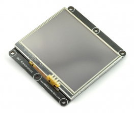
Display TE35
The configurations for the display:
Width = 320,
Height = 240,
PixelClockRate = 15 * 1000 * 1000,
PixelPolarity = false,
OutputEnablePolarity = true,
OutputEnableIsFixed = true,
HorizontalFrontPorch = 51,
HorizontalBackPorch = 29,
HorizontalSyncPulseWidth = 41,
HorizontalSyncPolarity = false,
VerticalFrontPorch = 16,
VerticalBackPorch = 3,
VerticalSyncPulseWidth = 10,
VerticalSyncPolarity = false,
Distance US3
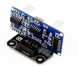
A very common ultrasonic sensor that works by sending a pulse on the trig Pin4 and measuring the response time on echo Pin3.
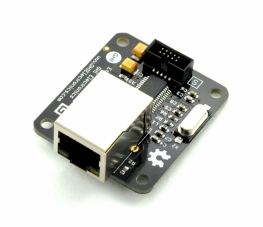
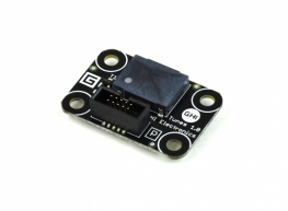
Ethernet ENC28
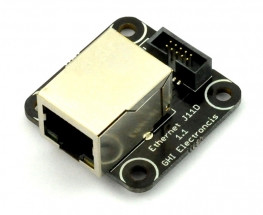
Ethernet J11D
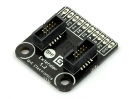
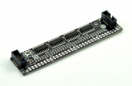
Extender
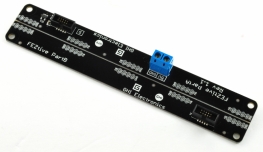
FEZtive
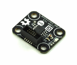
Flash
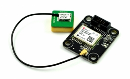
GPS
GasSense
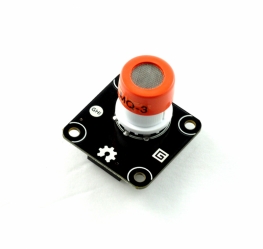
This module can host several different air sensors, like Alcohol and CO2.
The sensor has an internal heater on pin 4 that needs to be enabled and then it is a simple analog read on pin 3.
Gyro
HD44780
See the Character Display Module
HubAP5
No hub support is currently planned.
IO60P16
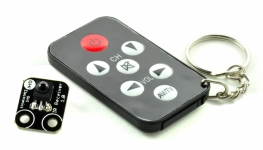
IR Receiver
Joystick
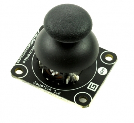
The Joystick module has two analog inputs for X (pin 4) and Y (pin 5) position. Pressing the knob also works like a button (pin 3).
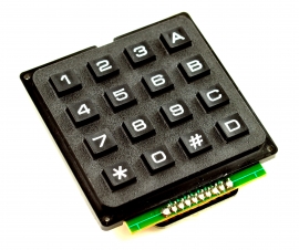
Keypad KP16
LED 7C
An LED that can be set to one of 7 colors, 8 if you count off!
LED 7R
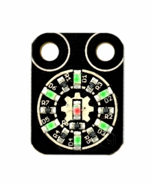
This is a ring of 6 LEDs and a 7th center LED. Reference the LED 7C module for using pins.
Center LED: pin 9 LEDs going clockwise starting from LEDs D1 to D6 on the board D1, D2, D3, D4, D5, D6 are pins 3 to 8 respectively.
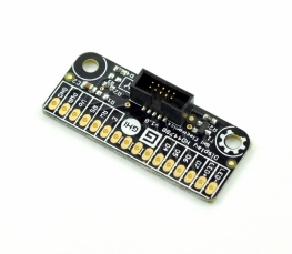
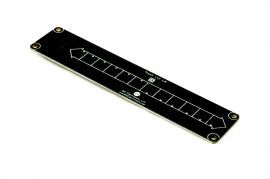
LED Strip
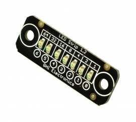
A strip of 7 LEDs, connected to pins 3 through 9. Reference the LED 7C module for using pins.
Light Sense
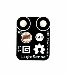
Simply using analog on pin 3. Use the same code as the potentiometer.
Load
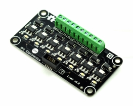
Each one of the 7 GPIO pins are connected to a transistor to handle a load, like a motor.
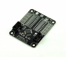
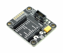
MaxO
Shift registers used to take serial SPI data and put on parallel pins, perfect for driving tons of LEDs!
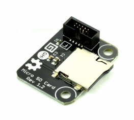
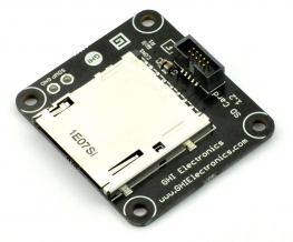
MicroSD Card
Moisture
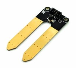
This is a simple analog input measuring the direct resistance (moisture) on pin 3. An enable pin needs to be activated on pin 6.
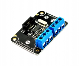
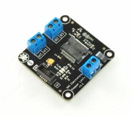
Motor Driver
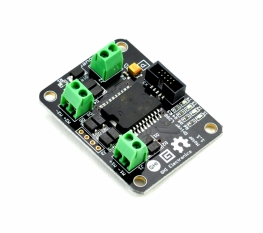
The Motor Driver Module uses L298 H-bridge that can drive two motors up to 4A.
Pin 6: Motor A Direction (GPIO)
Pin 7: Motor A Speed (PWM)
Pin 8: Motor B Direction (GPIO)
Pin 9: Motor B Speed (PWM)
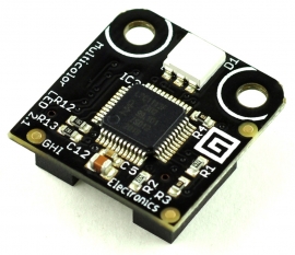
Multicolor LED
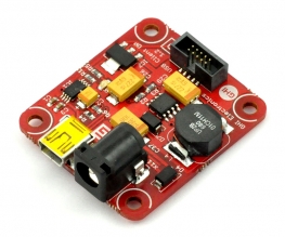
Music
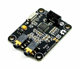
The Music Module uses the popular VS1053 decoder chip that decodes MP3, WMA, OGG, MIDI and WAV files.
Null Modem
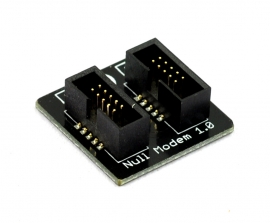
No driver is needed.
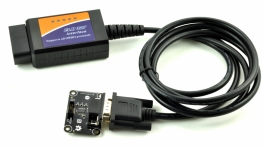
OBD II
OneWire X1
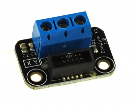
A breakout with a terminal block for easily connecting OneWire devices, specifically the common temperature probes.
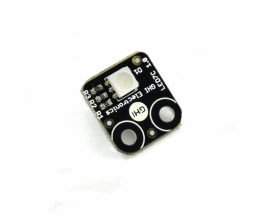
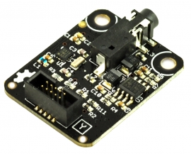
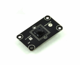
PIR
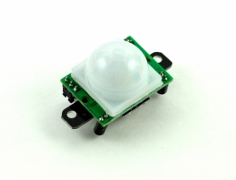
Motion detection. Simply pin 3 changes its state when it detects motion.
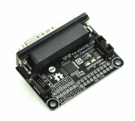
Parallel CNC
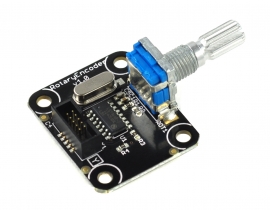
Potentiometer
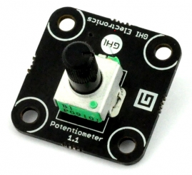
The Potentiometer module is simply a variable resistor connected to pin3. Rotating its knob will result in an analog value changing from min to max.
Pulse Count
Pulse InOut
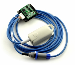
Pulse Oximeter
RFID Reader
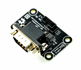
RS232
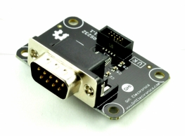
Simply a serial port.
RS485
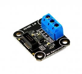
Simply a serial port.
Radio FM1
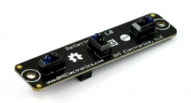
Reflector R3
Relay ISOx16
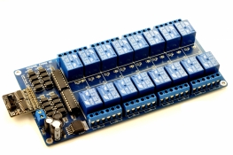
An array of 16 relays. Operate similar to the MaxO module.
Relay X1
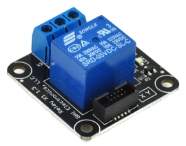
Simply set pin 3 high to activate the relay.
Rotary H1
SD Card
S-Plus
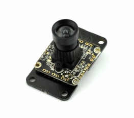
Serial Camera
Stepper L6470
TempHumidity
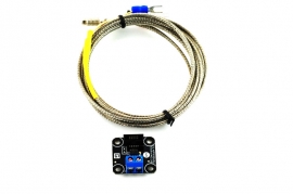
Thermocouple
Touch C8
Touch L12
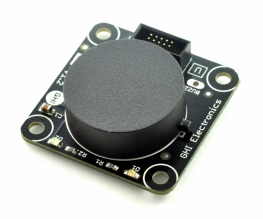
Tunes
The Tunes Module is a tiny speaker that is connected to pin 9. Use PWM to generate sounds
UC Battery 4xAA
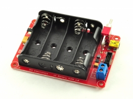
No driver is needed.
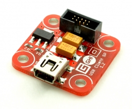
USB Client DP
No driver is needed.
USB Client SP
No driver is needed.
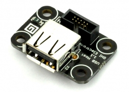
USB Host
USB Serial
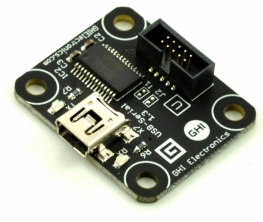
Simply, a serial port.
USB Serial SP
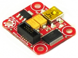
Simply, a serial port.
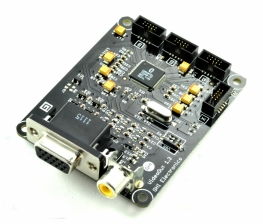
VideoOut
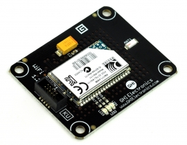
WiFi RN171
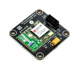
WiFi RS21
XBee Adapter
Simply, a serial port. From there a driver like https://xbee.codeplex.com/ will help.