The UCM Standard
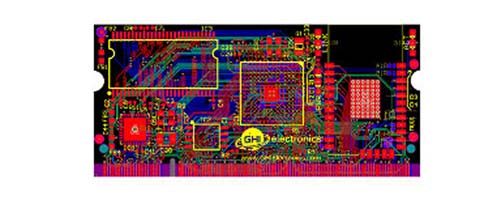
The UCM Standard defines a consistent hardware and software interface for the most widely used microcontroller peripherals. Universal Compute Modules are based on the 200 pin SO-DIMM form factor. They adhere to a standard pinout across models making it easy to change modules to adapt to the needs of your product.
When designing a product, consider following thee UCM standard pinout. This will make your design compatible with any of the UCM modules.
Software also becomes more portable with the UCM standard. For example, our TinyCLR OS provides a library to automatically map the UCM standard names to the underlying system so that your program can use the UCM standard names only, making changing to a different module very easy.
The SO-DIMM Socket
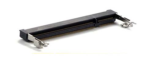
All of our UCMs use the same 200 pin SO-DIMM socket that was originally made for DDR2 memory modules. The fastest way to get started with UCMs is by using the optional boards and displays described on the UCM Development Options page. You can also incorporate any of our UCMs into your own custom design by adding the appropriate SO-DIMM socket to your circuit board.
Tip
Make sure to expose the required pins in your design. Specific pins are needed for device programming, updates, recovery, and WiFi firmware updates. See device specifications for details.
SO-DIMM stands for Small Outline Dual Inline Memory Module. There are two different 200 pin SO-DIMM sockets, those made for DDR memory and those made for DDR2 memory. They are identical except for the orientation notch which is in a slightly different position. These sockets are not interchangeable. There is also a 204 pin SO-DIMM socket for DDR3 memory with the notch positioned closer to the center of the module.
Note
Our UCMs are only compatible with DDR2 type 200 pin SO-DIMM sockets.
Here is a link to the manufacturer's web page for the connector we use on our boards: EMBOSS ASSY DDR2 SODIMM SOCKET 200P 5.2H
Peripherals
| Peripheral | Up to Max |
|---|---|
| UART (Universal Asynchronous Receiver/Transmitter) | 4 |
| UART HS (Handshaking) | 2 |
| I2C (Inter-Integrated Circuit) | 2 |
| SPI (Serial Peripheral Interface) | 2 |
| CAN (Controller Area Network) | 2 |
| SDIO (SD Card) | 1 |
| ADC (Analog to Digital Converter) | 8 |
| PWM (Pulse Width Modulation) | 8 |
| GPIO (General Purpose Input/Output) | 12 |
| IRQ (Interrupt Request Capable GPIO) | 4 |
| USB Client | 1 |
| USB Host | 1 |
| LCD (TFT Controller - 16bpp or 24bpp) | 1 |
| Ethernet PHY (Ethernet Physical Layer) | 1 |
| DCMI (Digital Camera Interface) | 1 |
| VBAT (Battery Backup for RTC) | 1 |
| JTAG (Debug Serial Port) | 1 |
*Available peripherals vary by model
Note that the system defines 12 GPIOs that are free from any other functions but most other peripheral pins also support GPIO, giving the user several more GPIO pin options -- keep in mind the standard does not guarantee this though.
Tip
The TinyCLR tutorials are a good resource on using these peripherals.
UART (Universal Asynchronous Receiver Transmitter)
UART is used to implement moderate speed full duplex asynchronous serial communication. It is usually used for peer to peer communication between only two devices. It can transfer data using only one wire for each direction if both devices share a common ground.
UART HS (Handshaking)
UART with handshaking is a configuration which allows the host and client to negotiate data transfer via Ready to Send (RTS) and Clear to Send (CTS) signals (two additional wires) to prevent missed data.
I2C (Inter-Integrated Circuit)
I2C is a multi-master, multi-slave, packet switched, half duplex serial communication bus typically used for attaching peripheral ICs to processors and microcontrollers in short-distance, intra-board communication. It uses two wires and has a slower maximum speed than SPI.
SPI (Serial Peripheral Interface)
SPI is a synchronous serial communication interface used for short distance communication. It uses a master-slave protocol. When using TinyCLR, the processor running TinyCLR is always configured as the master. SPI needs at least three wires and usually needs an additional line (chip select) for each slave. It can communicate much faster than either UART or I2C.
CAN (Controller Area Network)
A robust bus standard that originated in the automotive field and works very well in high noise environments. It allows microcontrollers and devices to communicate with each other in applications without a host computer. It is a message-based multi-master protocol and generally uses only two wires. Speed is up to one megabit per second but limited by bus length.
SDIO (SD Card)
SDIO (Secure Digital Input Output) is an interface used for reading from and writing to SD cards.
ADC (Analog to Digital Converter)
ADCs are used to measure an analog voltage level by converting it to a digital value.
PWM (Pulse Width Modulation)
PWM is a method of generating a square wave signal of uniform frequency with variable duty cycle. PWM is often used to generate analog voltages, but has many other uses such as generating digital pulses for driving servo motors or driving infrared LEDs for communication.
GPIO (General Purpose Input/Output)
GPIOs are the digital I/O pins that allow the user to interface with basic devices such as buttons (input) or LEDs (output). GPIOs are very versatile and can also be used to perform more advanced communication and control duties.
IRQ (Interrupt Request Capable GPIO)
IRQ capable GPIO pins can be programmed to interrupt a program when the input to the pin changes. For example, an IRQ could be used by a WiFi module to tell the processor that the WiFi module is receiving data. The processor would then stop what it is doing to get the data from the WiFi module.
USB Client
Used to communicate with a USB host. Often used to program and debug embedded devices.
USB Host
Used to communicate with one or more USB clients. Typically used to communicate with various devices such as a mouse, keyboard, camera, etc.
LCD (TFT Controller - 16bpp or 24bpp)
An interface providing communication with a TFT LCD (thin-film-transistor liquid-crystal display). The number of data lines connected determines the number of bits per pixel (bpp), which determines the number of colors that can be displayed.
Ethernet PHY
Ethernet PHY is the Ethernet physical (hardware) layer. It provides the Tx and Rx signals for the Ethernet connector.
DCMI (Digital Camera Interface)
A standard interface for compatible digital cameras.
VBAT (Battery Backup for RTC)
VBAT is used to provide battery voltage to a microcontroller's real time clock. It allows the microcontroller to keep the correct time when the main power to the controller is disconnected (the device is turned off).
JTAG
JTAG is a serial interface which allows communication between the processor and a host computer. It is built into the microcontroller and provides a means of software debugging including the ability to stop program execution, single step through program instructions, and read and write to memory and processor registers.
Pin Assignments
| SO-DIMM Pin | Universal Compute Standard |
|---|---|
| 1 | AGND |
| 2 | Ethernet TX- |
| 3 | Module Specific 1 |
| 4 | Ethernet TX+ |
| 5 | Analog VREF- |
| 6 | Ethernet RX- |
| 7 | Reserved |
| 8 | Ethernet RX+ |
| 9 | Reserved |
| 10 | Indicator A |
| 11 | Indicator B |
| 12 | Reserved |
| 13 | GND |
| 14 | DCMI D0 |
| 15 | DCMI D1 |
| 16 | DCMI D2 |
| 17 | DCMI D3 |
| 18 | DCMI D4 |
| 19 | DCMI D5 |
| 20 | Analog 3.3V |
| 21 | DCMI D6 |
| 22 | DCMI D7 |
| 23 | DCMI VSYNC |
| 24 | DCMI HSYNC |
| 25 | DCMI PIXCLK |
| 26 | DCMI XCLK |
| 27 | GND |
| 28 | PWM E |
| 29 | PWM F |
| 30 | PWM G |
| 31 | PWM H |
| 32 | Analog VREF+ |
| 33 | Reserved |
| 34 | 5V |
| 35 | Module Specific 4 |
| 36 | Module Specific 5 |
| 37 | Module Specific 6 |
| 38 | Module Specific 7 |
| 39 | Module Specific 8 |
| 40 | GND |
| 41 | GND |
| 42 | LCD 24bpp R0 |
| 43 | LCD 24bpp R1 |
| 44 | LCD 24bpp R2 |
| 45 | LCD 24bpp G0 |
| 46 | 3.3V |
| 47 | LCD 24bpp G1 |
| 48 | LCD 24bpp B0 |
| 49 | LCD 24bpp B1 |
| 50 | LCD 24bpp B2 |
| 51 | GND |
| 52 | Module Specific 9 |
| 53 | Reserved |
| 54 | Reserved |
| 55 | Reserved |
| 56 | 5V |
| 57 | IRQ A |
| 58 | IRQ B |
| 59 | IRQ C |
| 60 | 3.3V |
| 61 | IRQ D |
| 62 | GPIO A |
| 63 | GPIO B |
| 64 | GPIO C |
| 65 | GND |
| 66 | GPIO D |
| 67 | GPIO E |
| 68 | GPIO F |
| 69 | GPIO G |
| 70 | 5V |
| 71 | Reserved |
| 72 | 3.3V |
| 73 | I2C B SDA |
| 74 | I2C B SCL |
| 75 | UART C TX |
| 76 | UART C RX |
| 77 | UART D TX |
| 78 | UART D RX |
| 79 | GND |
| 80 | Reserved |
| 81 | Reserved |
| 82 | Reserved |
| 83 | Reserved |
| 84 | Reserved |
| 85 | Reserved |
| 86 | 5V |
| 87 | USB Device ID |
| 88 | 3.3V |
| 89 | UART B TX |
| 90 | UART B RX |
| 91 | ADC A |
| 92 | GPIO H |
| 93 | SPI B MISO |
| 94 | SPI B MOSI |
| 95 | GND |
| 96 | SPI B SCK |
| 97 | ADC B |
| 98 | CAN A TD |
| 99 | CAN A RD |
| 100 | CAN B TD |
| 101 | CAN B RD |
| 102 | UART HS A TX |
| 103 | UART HS A RX |
| 104 | ADC C |
| 105 | PWM A |
| 106 | 3.3V |
| 107 | SYS A |
| 108 | Module Specific 2 |
| 109 | Module Specific 3 |
| 110 | ADC D |
| 111 | SYS C |
| 112 | PWM B |
| 113 | GND |
| 114 | ADC E |
| 115 | I2C A SDA |
| 116 | I2C A SCL |
| 117 | UART A RX |
| 118 | UART A TX |
| 119 | GPIO I |
| 120 | UART HS A RTS |
| 121 | UART HS A CTS |
| 122 | GPIO J |
| 123 | SD Card D0 |
| 124 | 3.3V |
| 125 | SD Card CMD |
| 126 | SD Card CLK |
| 127 | SD Card D1 |
| 128 | SD Card D2 |
| 129 | SD Card D3 |
| 130 | PWM C |
| 131 | GND |
| 132 | GPIO K |
| 133 | PWM D |
| 134 | SYS B |
| 135 | SYS D |
| 136 | GPIO L |
| 137 | Module Specific 10 |
| 138 | UART HS B RTS |
| 139 | UART HS B CTS |
| 140 | UART HS B TX |
| 141 | UART HS B RX |
| 142 | 3.3V |
| 143 | LCD VSYNC |
| 144 | LCD HSYNC |
| 145 | LCD CLK |
| 146 | LCD DE |
| 147 | Module Specific 11 |
| 148 | SD Card CD |
| 149 | Module Specific 12 |
| 150 | Reserved |
| 151 | GND |
| 152 | LCD B3 |
| 153 | LCD B4 |
| 154 | LCD B5 |
| 155 | LCD B6 |
| 156 | LCD B7 |
| 157 | ADC F |
| 158 | ADC G |
| 159 | ADC H |
| 160 | 3.3V |
| 161 | LCD G2 |
| 162 | LCD G3 |
| 163 | LCD G4 |
| 164 | LCD G5 |
| 165 | LCD G6 |
| 166 | Module Specific 13 |
| 167 | Indicator C |
| 168 | LCD R7 |
| 169 | GND |
| 170 | LCD G7 |
| 171 | LCD R3 |
| 172 | LCD R4 |
| 173 | LCD R5 |
| 174 | LCD R6 |
| 175 | SPI A SCK |
| 176 | SPI A MISO |
| 177 | Module Specific 14 |
| 178 | SPI A MOSI |
| 179 | Module Specific 15 |
| 180 | 3.3V |
| 181 | Module Specific 16 |
| 182 | Module Specific 17 |
| 183 | VBAT |
| 184 | Module Specific 18 |
| 185 | GND |
| 186 | GND |
| 187 | RESET |
| 188 | USB Host D+ |
| 189 | JTAG RTCK |
| 190 | USB Host D- |
| 191 | JTAG TDO |
| 192 | 3.3V |
| 193 | JTAG NTRST |
| 194 | USB Device D+ |
| 195 | JTAG TDI |
| 196 | USB Device D- |
| 197 | JTAG TCK (SWCLK) |
| 198 | GND |
| 199 | JTAG TMS (SWDIO) |
| 200 | Indicator D |
Want to quickly build your prototype? Check out the UCM Development Options.
You can also visit our main website at main website and our community forum.